Using Logical Clocks To Take Global Snapshots
This page describes an algorithm that uses logical time to determine global snapshots. The state at which all agents are at the same logical time \(t\) is a global snapshot. The algorithm used for logical time can also be used with epochs.
The Problem
Design an algorithm that computes global snapshots using logical clocks.
How Should You Solve the Problem?
Strategy
A strategy to develop any algorithm that deals with global snapshots is: Start with definition of consistent cuts.Observation
For any \(t\), define the past at \(t\) in a
computation as the set of steps with logical time at most \(t\),
and define future at \(t\)
as the set of steps with logical time greater than
\(t\).
(past at logical time \(t\), future at
logical time \(t\)) is a consistent cut.
Proof
From the definition of logical time, paths in the dataflow graph are from from smaller to higher logical times. Therefore all paths to steps inpast at logical
time \(t\) are from steps in past at logical
time \(t\).
State at Logical Time \(t\)
The state at logical time \(t\) is the state at the consistent cut
(past at logical time \(t\), future at
logical time \(t\)), and is given by the labels of edges from steps in
past at logical time \(t\) to steps in
future at logical time \(t\).
Example: State at Logical Time \(t\)
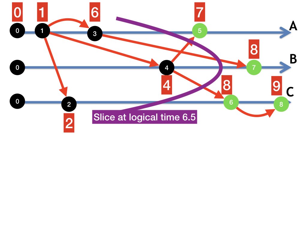
Figure 1 illustrates the state at logical time 6.5 of the computation shown in figure 1. The curved purple line represents the boundary that separates the past of the cut from its future. Past steps are colored black while future steps are colored green. The states of agents and channels at logical time \(t = 6.5\) are given by the labels of the edges that cut the purple line.

The point at which the cut boundary -- the purple line -- intersects the timeline for agent \(A\) can be thought of as the point in \(A\)'s computation at which the logical time is exactly 6.5. The cut boundary intersects the edge from the step at \(A\) with logical time at most 6.5 to the step with logical time greater than 6.5. In this example, the cut boundary intersects the edge on \(A\)'s timeline from step 3 to step 5.
The message edge from step 3 to step 7 represents a message sent along the channel from \(A\) to \(B\) in the past that is received in the future. In this example, the state of the channel \((A, B)\) is the sequence consisting of a single message which is the label of this edge.
Global Snapshot Algorithm to Record the State at a Logical Time
An algorithm to record the state at logical time \(t\) follows directly from the definition of the state at logical time \(t\).
- Each agent takes its local snapshot -- i.e. records its state -- after a step with logical time at most \(t\) and before a step with logical time greater than \(t\).
- An agent records the state of an input channel as the sequence of messages with timestamps atmost \(t\) that the agent receives when its logical clock exceeds \(t\).
Epochs
The algorithm used with logical time can also be used with epochs because of the observation analogous to that of the observation we made for logical time.Observation
For any \(t\), define the past at \(t\) in a
computation as the set of steps with epoch at most \(t\),
and define future at \(t\)
as the set of steps with epoch greater than
\(t\).
(past at epoch \(t\), future at
epoch \(t\)) is a consistent cut.
Using Imperfect Clocks in Distributed Algorithms
Intuition
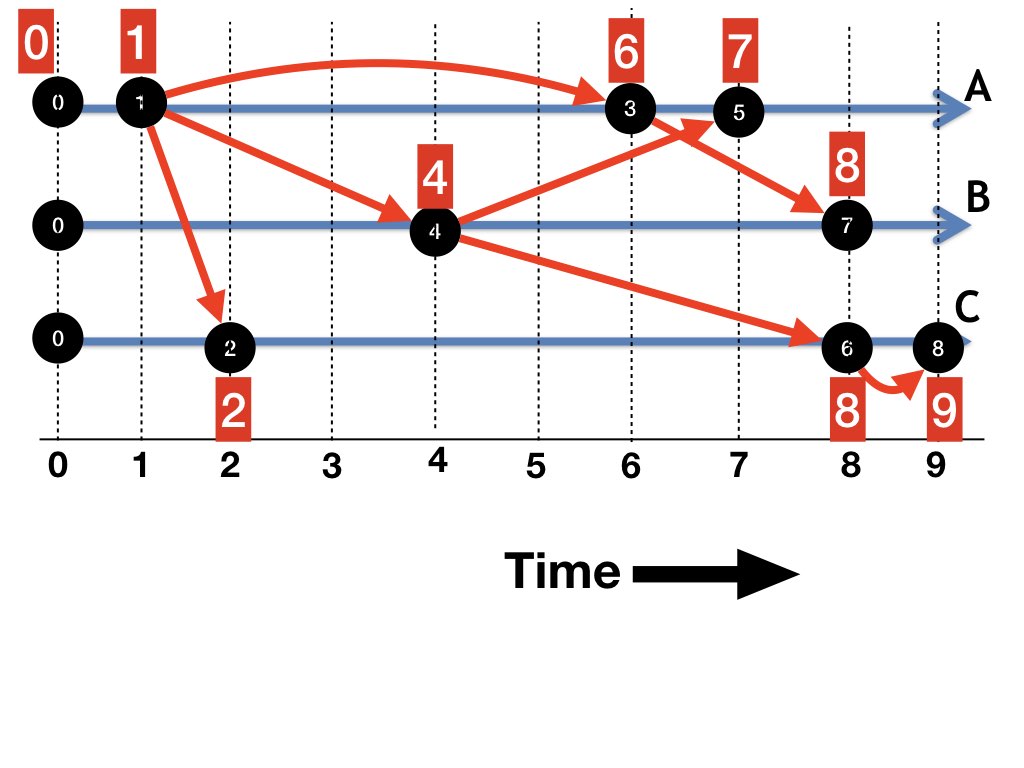
We will design some algorithms with logical time playing the role of real time. Figure 2 shows the computation in figure 1 with the horizontal axis representing logical time. The dataflow graphs are identical in figures 1 and 2; however, in figure 2 the position of a step with logical time \(t\) is shown at a distance of \(t\) units from steps at time \(0\).

Think of logical time as continuous, just as real time is continuous. In this example, points at logical times \(6.5\) and \(6.6\), at agent \(A\), refer to the same edge -- the edge from step 3 to step 5. It helps intuition, however, to think of the point at logical time \(6.6\) at agent \(A\) as a point 0.1 time units to the right of of the point with logical time \(6.5\) at \(A\).
The consistent cut at logical time \(6.5\) is represented in figure 2 by the vertical line at time \(6.5\). The steps to the left of the line is the past at logical time \(6.5\), and the steps to the right of the line is the future at that time.
Physical and Logical Clocks
Operating systems maintain clocks. Some have atomic clocks or other high-fidelity clocks that use Precision or Network Time Protocols (PTP, NTP). With high-fidelity clocks, a message sent when the sender's clock is at \(t\) will almost always be received when the receiver's clock is later than \(t\). High-fidelity clocks almost always obey the logical clock requirement.
We cannot rule out the possibility that a message sent when the sender's clock is later than \(t\) is received when the receiver's clock is earlier than \(t\). If this happens the logical clock requirement is violated because data flows from a step at a later time to a step at an earlier time.
To prevent physical clocks from violating the logical clock requirement we correct physical clocks using the logical clock algorithm. If an agent receives a message with timestamp \(T\) when the agent's clock is at \(T'\), then if \(T' < T\), the agent corrects its clock -- i.e. moves its clock forward to a value greater than \(T\).
Such "logically-corrected physical clocks" have the following properties that we use in designing algorithms:
- Clocks tick forward forever: For all \(t\), there is a point in an infinite computation at which clocks of all agents exceed \(t\).
- Sequences of steps in ascending order of time are computations where the time of a step is determined by the local clock of the agent in which the step occurs.
Next
The next few pages describe applications of global snapshots. We begin with Termination Detection.
K. Mani Chandy, Emeritus Simon Ramo Professor, California Institute of Technology